My last Arduino lesson was the first one where I had to build a circuit but also control it with a programmed sketch.
The Circuit
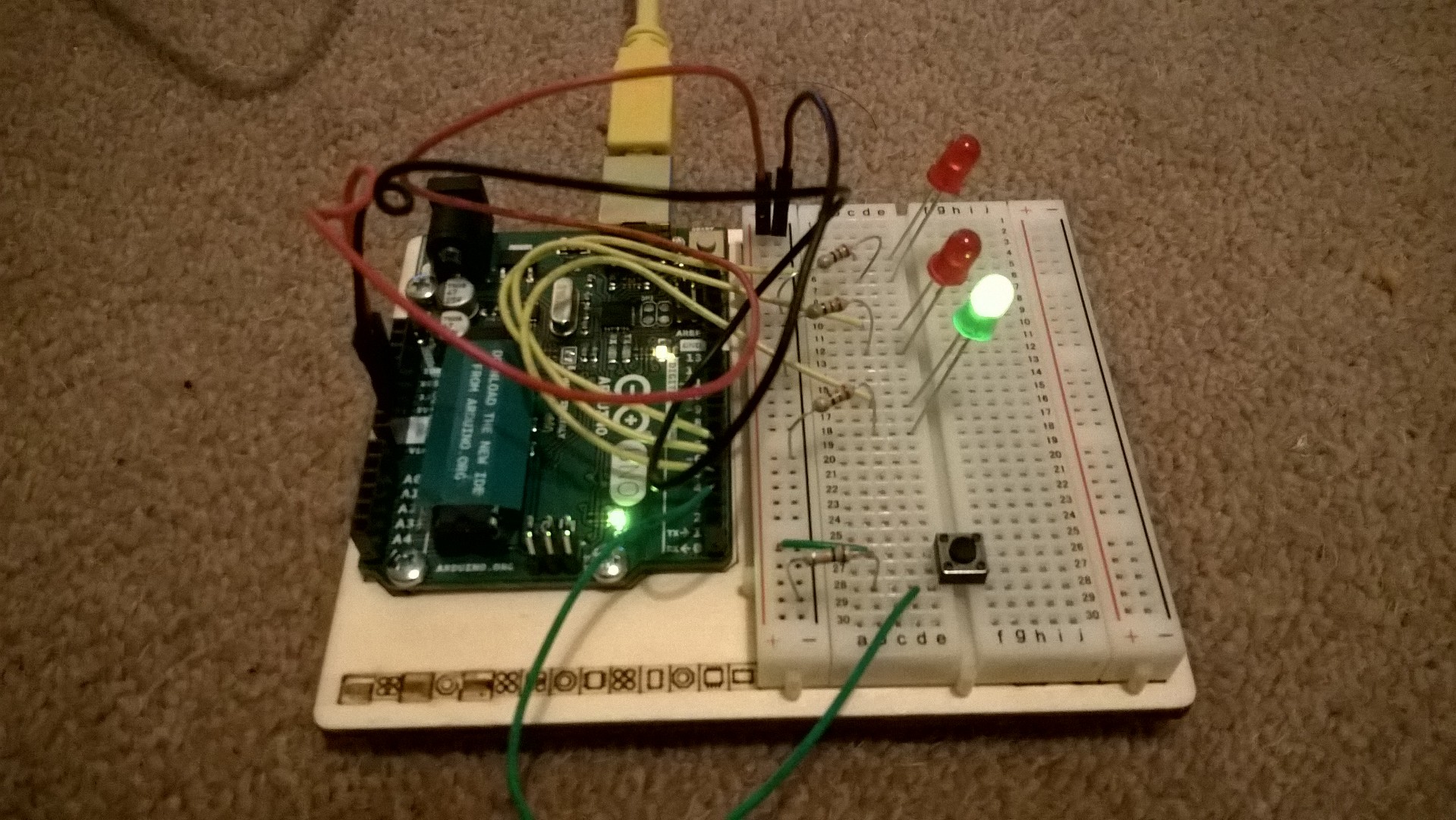
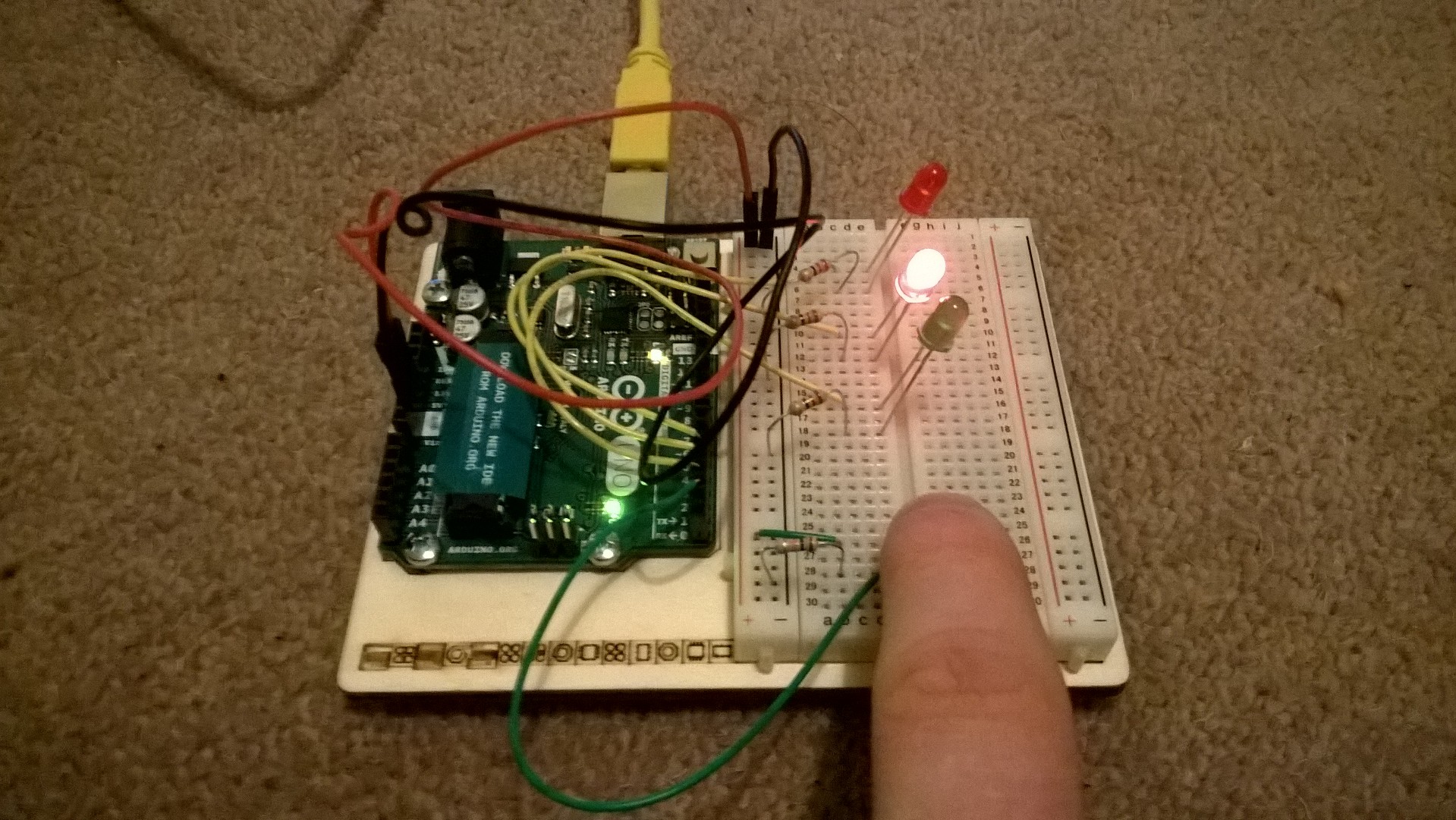
In this circuit there were three LEDs, resistors and a push switch. When the circuit has power the green LED is lit, but when the push switch was pressed the two red LEDs flash.
To achieve this, the LEDs and the switch in this circuit had to be connected to the pins on the Arduino. This allows the Arduino to control if the LEDs have voltage going to them or not. Pins 0 and 1 are used for connecting to the computer so its useful to start at pin 2.
Writing the Sketch
Each sketch needs two main functions in order to work;
void setup(){
}

void loop(){
}
Setup is run once when the program starts and unsurprisingly loop repeats throughout the program running. In the setup of the sketch the numbers of the used pins and if they are to be used as input or an output.
pinMode(5, OUTPUT);
pinMode(2, INPUT);
In the loop you can check if the switch is pressed down by using the digital read method and passing in the pin number of the input.
int buttonPressed = digitalRead(2);
As it is a digital input the value from digital read can be asigned to an int as it will return 0 or 1.
Similarly, digital write also takes a pin number as an argument but also if you want the pin to be set to HIGH (1) or LOW (0).
digitalWrite(3, HIGH);
My Full Sketch
int switchState = 0;

void setup() {
    // put your setup code here, to run once:
    pinMode(3, OUTPUT);
    pinMode(4, OUTPUT);
    pinMode(5, OUTPUT);
    pinMode(2, INPUT);
}

void loop() {
    // put your main code here, to run repeatedly:
    switchState = digitalRead(2);

    if(switchState == LOW){
        digitalWrite(3, HIGH);
        digitalWrite(4, LOW);
        digitalWrite(5, LOW);
    }
    else{
        digitalWrite(3, LOW);
        digitalWrite(4, LOW);
        digitalWrite(5, HIGH);

        delay(250);
        digitalWrite(4, HIGH);
        digitalWrite(5, LOW);
        delay(250);
    }
}
Apart from learning how a sketch is built and what happens when it runs, this lesson also taught me more about resistors. Here the example circuit had each LED connected to the resistor on the ground side of the circuit. As long as the circuit is wired in series it doesn’t matter where the resistor is connected.